Thermal camera survey room by room workflow: a Room-by-Room Thermal Camera Survey Workflow for UK Homes
A practical thermal camera survey room by room workflow starts with a clear indoor–outdoor temperature difference, follows the same route through every space, checks doors, windows, junctions and heating in a fixed order, and records where each image was taken so cold spots can be reviewed and followed up sensibly.
Prepare the indoor-outdoor temperature difference
Before you begin, aim for a substantial difference between indoor and outdoor temperatures. Council guidance notes that a colder outdoor temperature improves home-survey results, and that a clear indoor–outdoor contrast helps thermal patterns show up more clearly.
Keep heating steady for a period before you survey so rooms are not still warming or cooling mid-route. Close external doors and windows while you work so draughts and outdoor air do not blur the picture. Treat the camera as a screening tool: patterns suggest where to look next, not proof of damp, wiring faults, insulation failure or regulatory compliance.
Create a fixed survey route
A repeatable heat loss inspection depends on walking the same path each time. Decide a home thermal survey sequence in advance—for example ground floor clockwise, then first floor, then loft hatch or other accessible voids last—and stick to it.
- Start at the same entrance or hallway every time.
- Survey each room from the doorway, then the perimeter, then the centre.
- Finish with external-facing walls and any known cold corners before moving on.
- Use the same viewing height and distance where practical so images remain comparable.
A fixed route makes it easier to compare today’s images with a later visit after draught-proofing or insulation work.
Doors, windows and junctions checklist
Use a thermal imaging room checklist for openings and junctions, where heat loss and air leakage often show first.
- Door frames, thresholds and letterboxes.
- Window frames, glazing edges and trickle vents.
- Skirting-board and wall junctions.
- Ceiling–wall corners and bay-window returns.
- Loft hatches, pipe penetrations and service voids where accessible and safe.
Thermal imaging can help identify cold spots and insulation gaps around these details. Mark anything that looks cooler than neighbouring surfaces for a closer look later, without assuming a single cause from the image alone.
Heating and radiator observations
Thermal cameras can reveal draughts, insulation gaps and heating problems when used with care. On radiators and heat emitters, look for uneven surface patterns, cool panels relative to nearby pipework, and cold returns that may warrant a simple follow-up check such as bleeding or balancing—always within your own competence and without claiming a diagnosis from the image alone.
Note whether radiators were on, off or recently switched when you took each image. Heating state changes how surfaces appear and should be written down with the photo.
Record image location and conditions
Good notes turn a set of pictures into a usable survey. For each capture, record:
- Room name and roughly where you stood.
- What you were aiming at (for example “north window frame” or “lounge radiator”).
- Indoor and outdoor conditions in plain language (heating on/off, cold evening outdoors).
- Any recent changes such as a door left open or a window aired.
South Cambridgeshire also stresses training to interpret thermal images. If you are new to the method, keep interpretations cautious and compare similar surfaces under similar conditions rather than reading every colour change as a fault.
Follow-up checks
Findings need appropriate follow-up. After the walk-through:
- Group images by room and by type of detail (openings, junctions, heating).
- Revisit the strongest cold spots in daylight with a simple tactile or visual check where safe.
- Prioritise low-risk improvements you can verify later with the same route—draught strips, loft-hatch seals, curtain gaps—before larger works.
- Seek a qualified tradesperson or energy adviser when patterns suggest structural, electrical or damp issues beyond a screening clue.
Repeat the same thermal camera survey room by room workflow after any changes so you can see whether patterns have shifted.
Next step
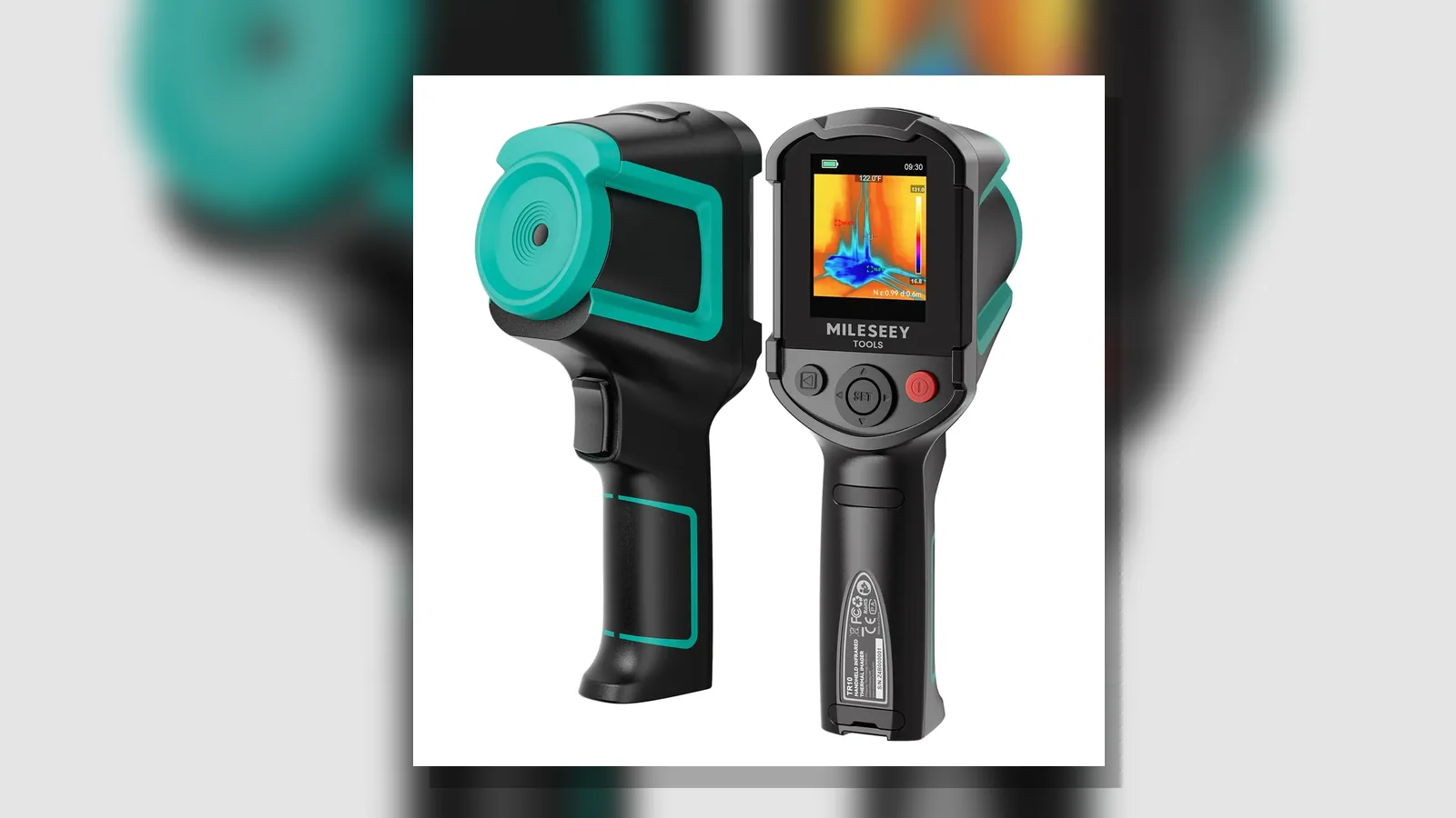
If you want a compact handheld infrared thermal imager for structured home checks, the MILESEEY TR10 (224 × 91 × 76 mm) is offered with a 12-month warranty on this site. Review the MILESEEY TR10 handheld thermal imager details when you are ready to choose a device for a room-by-room survey.
FAQ
Why does outdoor cold matter for a home thermal survey?
A colder outdoor temperature improves contrast between indoor surfaces and heat-loss paths, which helps draughts, insulation gaps and heating issues show more clearly during a survey.
Can a thermal image prove damp or failed insulation?
No. Thermal patterns are screening clues only. Cold spots and insulation gaps may need further checks; images alone do not prove damp, wiring defects, insulation failure or compliance.
What should stay the same on a repeat visit?
Use the same route, similar heating state, and comparable notes on location and conditions so you can judge whether follow-up work changed the pattern.
What product facts are confirmed for the TR10 on this page?
It is identified as a handheld infrared thermal imager, model TR10, with public-safe dimensions of 224 × 91 × 76 mm and a 12-month warranty term. Performance figures such as temperature range, accuracy or battery life are not stated here without further verification.